Face Mill Arbor
12/01/2020

The Objective
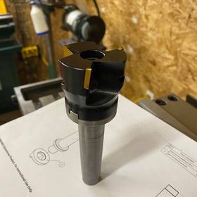
The objective of this project was to design and manufacture a #3 Morse taper (MT3) arbor for a 50.8 mm face mill. This was accomplished by designing a suitable arbor, creating a 3D model, selecting appropriate tolerances, and manufacturing the arbor with a lathe and mill. The result was an arbor with 0.038 mm total runout, which is more than accurate enough for the work I do in my home shop.The Details
Vertical milling machines have a tapered spindle that will accept any cutting tool with a matching tapered arbor. By way of a draw bar (a really long bolt), the arbor is pulled up into the spindle taper, allowing it to resist high lateral cutting forces without disengaging from the spindle. Typically, the spindle receives power from a motor via a belt or chain system. This power is directly transferred to the cutting tool which enables the operator to perform various milling operations.
The mill I own has a MT3 spindle. Modern mills typically use R8 or ISO30 tapers which makes purchasing tools for my mill difficult. This is what led me to design and machine my own arbor. The arbor I machined was designed for a 50.8 mm indexable face mill I purchased from Amazon. Face mills offer a fast and efficient way of removing material from large, flat surfaces which makes them invaluable tools to have in any machine shop.
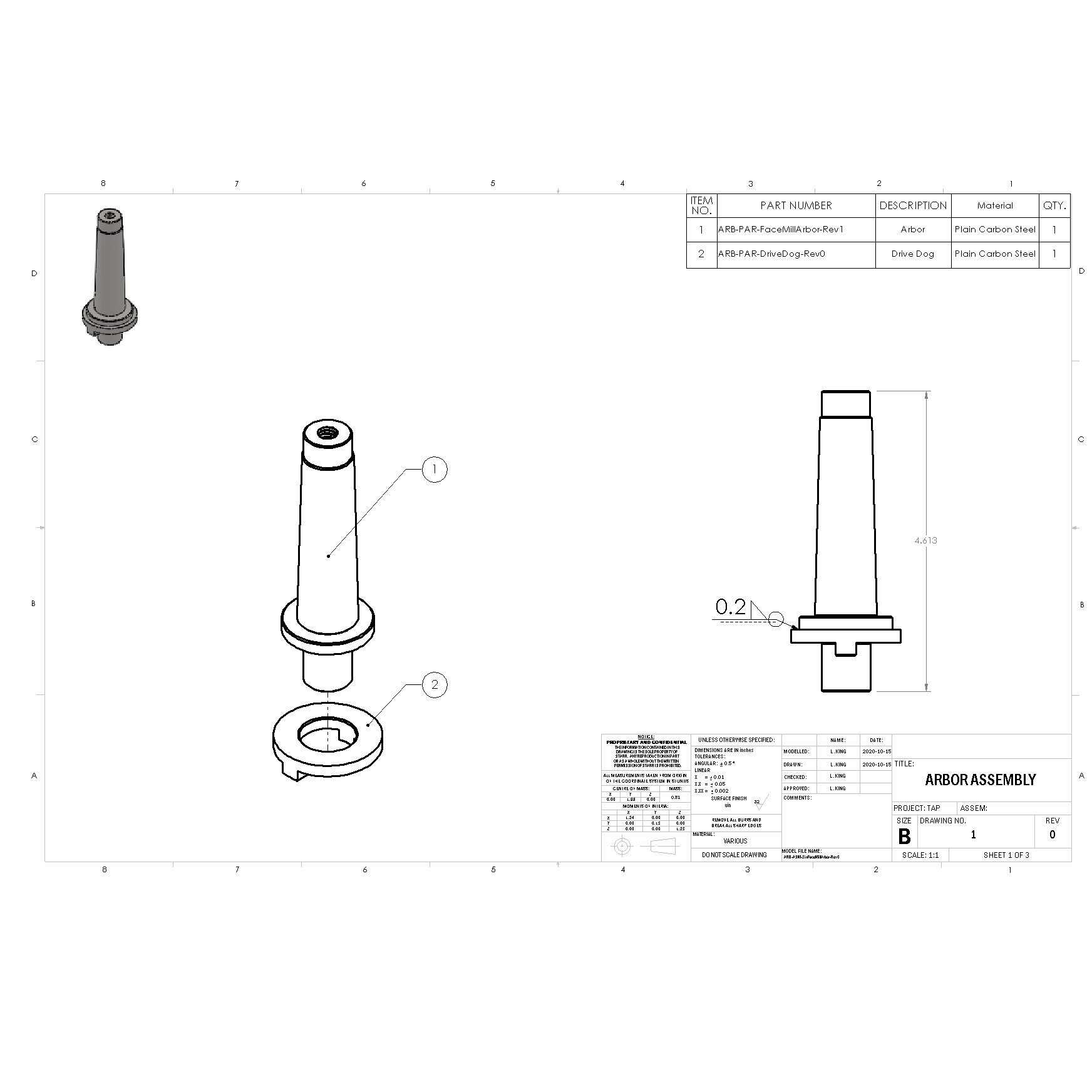
I created a list of specifications for the arbor which include the required features, material type, and the critical dimensions that would allow it to interface with the face mill. Given these specifications, I made several sketches, each pertaining to a different conceptual design. A winning design was selected based on simplicity, part availability, and learning opportunity. The design I chose is comprised of two pieces that are welded together and then machined to final dimension. I chose this design since it didn’t require any material or parts I didn’t already have on hand.

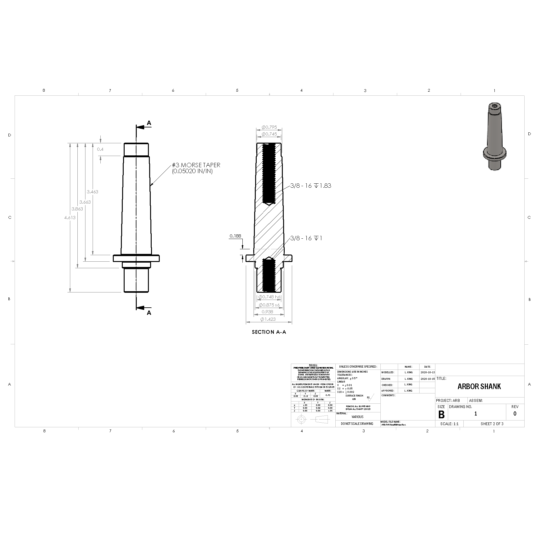
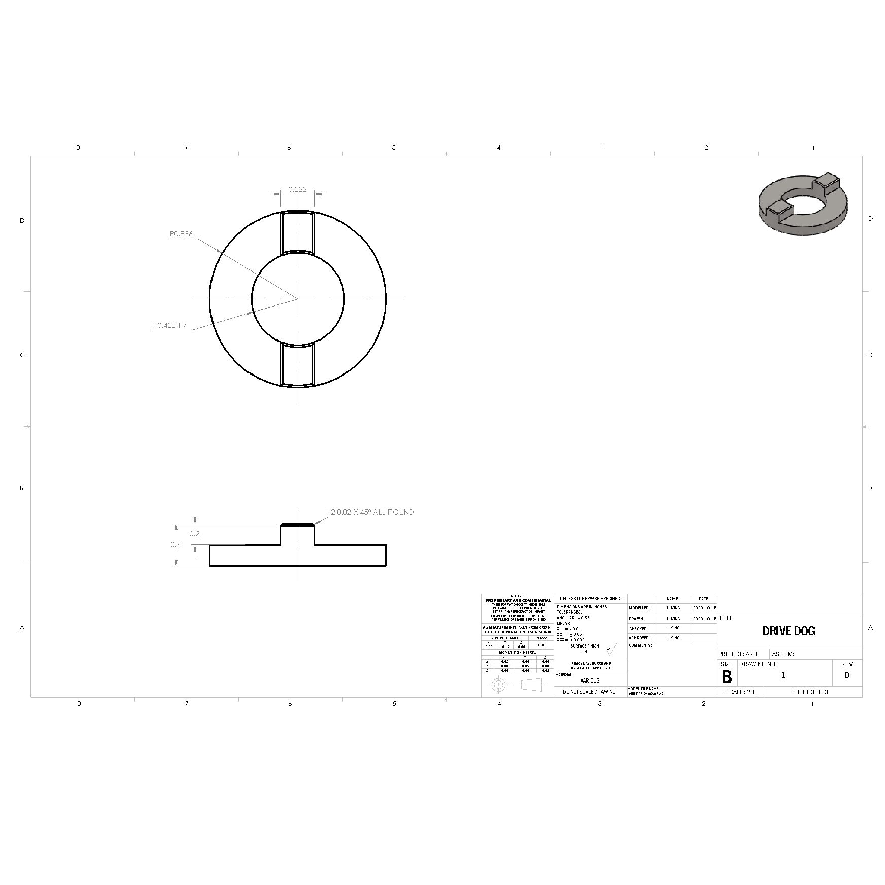
With the chosen concept in hand, I quickly modelled the design in SolidWorks and double checked my dimensions against the face mill. I then created engineering drawings for each component in my chosen design. Lastly, I specified limit fit tolerances to ensure proper fit and function. I specified a medium drive press fit to locate the drive dog to the arbor shank. I chose this over a locational clearance fit as I didn’t have the equipment at the time to achieve the required accuracy.

The first step in the manufacturing process was to align the compound slide on my lathe to the appropriate angle for turning a MT3 taper. In absence of a sine bar and gauge block set, I opted to use an MT3 dead center I had as my reference. By mounting this dead center between centers, I could align my compound slide correctly.

I began with a piece of 1018 round bar mounted in a 3-jaw chuck on the lathe then faced, and center drilled one face. The next step was to drill and tap for the 3/8 - 16 hole required for the drawbar. Following this operation, I turned down the shoulder, cut the MT3 taper, and cut a relief groove. With the taper now cut, I removed the arbor from the chuck and placed it in the tailstock of the lathe. This allowed me to center drill, drill, and tap the second 3/8 – 16 hole using the chuck. Finally, I mounted the arbor between centers and machined the remaining features.
Now for the drive dog. I began with a piece of 1018 round bar in a 3-jaw chuck. I faced and center drilled, drilled, and reamed a bore a few mm deeper than the thickness of the drive dog. I then turned the drive dog down to final dimension and parted the drive dog blank from the stock. Next, I set up the blank in a vise on the mill and used an edge finder to find the center of the blank. Using the centerline as reference, I machined the drive dog teeth into the blank with a 3/8” 2-flute endmill.
Next came assembly. I press fit the arbor shank to the drive dog and used my FCAW welder to fillet weld the two components together. I welded the components one quarter of the way around at a time, allowing sufficient cooling time in-between welds to prevent warping. Lastly, I mounted the assembled arbor between centers on the lathe and machined the now cooled weld to final dimension. This final step was critical in ensuring the arbor would be statically balanced, minimizing vibration during operation.
The Results
The resultant arbor functioned exactly as intended. With a few minor adjustments to the design, I can adapt it for use with any cutting tools I may need in the future. Overall, I am pleased with the final product and will look to this design for future tooling requirements. I checked the total runout (arbor runout + spindle runout) and found the runout to be 0.038 mm which is sufficient for the level of precision required in my shop. If I require higher precision in the future, I would first need to upgrade my metrology equipment i.e. (more precise micrometers, higher precision dial test indicator). The metrology equipment paired with fewer lathe setups would allow me to minimize the runout of the arbor.